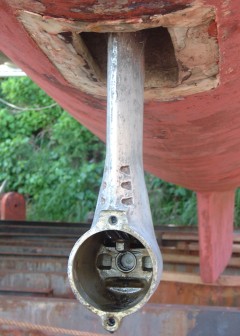
Saildrive gear-cluster removed
so we can replace the seals
|
Cruising Info Equipment Pages |
Sail Drives
Saildrives are often used on catamarans as they result in a very compact drive system. Multihulls have narrow hulls, so there's not enough room to walk around an engine, as there is on most monohulls. So a catamaran's engines are usually under the aft bunks, which usually doesn't leave much room for a gearbox, propeller shaft, external "A" bracket, and still have room for the rudder. Saildrives attach to the back of the engine and immediately go down through the bottom of the boat, sort of like the leg of an outboard motor. A pair of flexible seals (the main seal and a backup) keep water from flooding the engine room on Yanmar saildrives (Volvo saildrives only have a single seal). There are a handful of manufacturers who offer saildrives, but Volvo and Yanmar are probably the biggest, and the vast majority of saildrives we see are produced by those two manufacturers. Since we have Yanmar 4JH2CE engines and SD31 saildrives, the comments below are aimed primarily at Yanmar saildrives, but Volvo saildrives are similar enough that many of the comments apply to both.
The first 6 subjects we discuss are modifications we recommend folks do to their saildrives. The last 3 are procedures we've had to do recently and we thought we'd share our experiences, to help others. Subjects in this article include:
| 1. | Oil Header Tanks - - - - - - - - - - | How to make sure water doesn't get into your oil. |
| 2. | Secondary Seals - - - - - - - - - - | A cheap and easy way to help preserve your secondary seal. |
| 3. | Plastic Bag Screens - - - - - - - - | To prevent plastic bags from being sucked up the water inlets |
| 4. | Replacing the water inlet valve - | What was Yanmar thinking to use a multi‑turn valve here?!? |
| 5. | Sealing the leg with epoxy - - - - | This is not difficult to do, and will allow you to use the same paint on the whole of the bottom of your boat. |
| 6. | Saildrive Boots - - - - - - - - - - - - | Make your own instead of buying the flimsy official parts. |
| 7. | Remove & Replace - - - - - - - - - leg & main diaphragm |
Several tips on removing the leg, as well as how to replace the leg without pinching the O‑ring |
| 8. | Replacing input bearings - - - - - | When that seal starts leaking, this is what you have to do |
| 9. | Replacing upper drive-shaft - - - | This is surprisingly easy to do! |
 Saildrive gear-cluster removed so we can replace the seals |
Oil Header Tanks
Like virtually all manual gearboxes, saildrives are filled with 90W hypoid oil
(ideally, salt-resistant oil if you can find it). This oil is held in by a
pair of oil seals around the propeller shaft. Those oil seals will eventually wear out
so they need to be replaced periodically. They're usually fairly standard
seals, but replacing them means dismantling the bottom end of your saildrive and
then disassembling the gear-cluster to get at the seals - a messy and fiddly
business requiring some familiarity with the parts and procedures involved (and
sometimes requiring special tools).
But it's very important to service those seals before they leak. Since the saildrive is wholly below water level, the seawater on the outside is at a slightly higher pressure than the oil on the inside. This means that if the seals start to leak, seawater will enter the bottom of the saildrive and start turning your oil into mayonnaise. If this happens, you need to haul the boat out of the water and service the saildrive as soon as possible, before the seawater starts to corrode the gears and bearings.
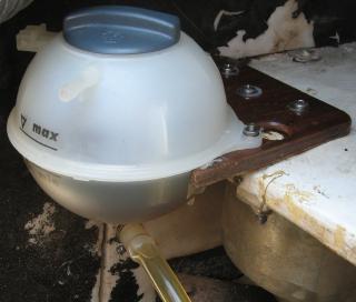 Oil tank & bracket in our port engine room |
In the Seychelles we ran into an excellent father/son machine shop, and I got to talking with the father. He'd seen a lot of marine equipment - in fact, he was refurbishing a turbocharger for a 5,000 horsepower diesel engine when I met him. When I explained this problem with the oil seals, he had an excellent idea: Put an oil header-tank as high up in the engine room as practicable, and run a hose from it to the saildrive. That way, the oil will be at a slightly higher pressure than the seawater. If the seals start to leak before their normal maintenance interval, all that will happen is that a bit of oil will leak out. You'll be able to see the oil level dropping slightly in the header tank, and that will tell you that you need to replace the oil seals the next time you haul the boat. But it's no longer an emergency!
We did this conversion in 2009 when we were in South Africa, and it has worked very well. The oil-fill / dipstick hole is a standard 1" (pipe?) thread, so we just removed the dipstick and replaced it with some pipe fittings to take the hose to the header tank. Using a plastic reducer where it goes into the saildrive will insure that you have no thread incompatibilities. Our SD31 required that the pipe extend above the body of the SD before putting in the elbow. We put a small valve in the hose so we can shut the header-tank oil off when we want to change the saildrive oil, so we don't change the oil in the header.
There are a couple of caveats here. First, the normal filler/dipstick keeps the pressure in when the oil heats up and expands. This strikes us as crazy, as it can force the oil past the propshaft seals. We can see no advantage to letting the pressure increase like that, and this header tank arrangement will keep the oil pressure much more constant, and at a lower pressure than a hot normal dive. This should be especially good for the oil seal on the input shaft from the engine.
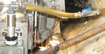 Oil piping into the saildrive - plastic & stainless steel |
Another issue is that the prop‑shaft oil seals should be turned around. Oil seals are direction sensitive. The flat side should go against what you don't care as much about, while the side with the spring (to hold the seal against the shaft) should go towards the side of the stuff you don't want to go past the seal. Changing the seals around is easy to do once you have the lower gear‑cluster apart. Some people we've talked to have put the 2 seals back to back, with the inner seal set to keep the oil in, and the outer seal set to keep the water out. We take this a step further. In our opinion, keeping the water out is the most important, so we put both seals with their backs towards the gears. If you do this, remember to remove the spring from any seals that will face the saltwater and replace them with an O‑ring that won't rust, especially if you use generic (non‑Yanmar) seals.
Finally, it will probably take a little while (several days of motoring) before all the air works its way out of the saildrive and up the hose, through the thick oil to the header tank. While this is happening, it may look like you're losing some oil, but it's just air coming out. Top it up, and it should stop eventually.
Secondary Seals
Yanmar saildrives have 2 flexible seals between the saildrive leg and the hull, to keep
the water out. The primary seal is a monster of thick rubber while the
secondary seal, above the primary seal, is much thinner, more like a car inner‑tube. The secondary
seal is what you actually see from above, and it's really only there for
emergencies, in case something happens to the
primary seal. But for the secondary seal to be effective, it has to be
able to survive whatever caused the primary seal to fail. It's unlikely that the primary seals will
simply "wear out" and develop a leak. Our seals have been in for 15 years, 4,000 hours of motoring, and
they look brand new. It's going to be an accident that causes that main seal to leak.
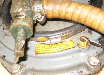 Hose clamp around our secondary saildrive seal |
In the Ha'apai Group of Tonga we had a big problem when we caught a rope in our starboard propeller and ripped that engine and saildrive clean off its mounts. This ripped the main seal that joins the saildrive to the hull, so we had water coming into the engine room. We were very lucky that the secondary seal had just popped off, and could be reset fairly easily. In fact, once we reset the secondary seal, it didn't even affect our cruising much, as we just continued cruising with our port engine (although anchoring was distressingly awkward).
It turns out that SunSail (who had managed Ocelot before we bought her) had replaced the $70 clip that Yanmar sells to hold that secondary seal with a large $5 stainless‑steel hose‑clamp. The Yanmar part holds the seal so securely that, had it been used, we might well have shredded the secondary seal as well as the primary! This would have been a REAL problem, especially since we were out in the boonies - a good 90 miles from what passes for civilization in Tonga.
As it was, a hose‑clamp is a bit too tall, so it can't be tightened up too
much or it slips off. It certainly holds the water out, but if you yank
hard on the hose‑clamp or
the seal, it will just pop off, instead of ripping the seal. This
allowed Jon to find the hose-clamp, loosen it a bit, make sure the seal was down
correctly, put the hose‑clamp over the seal, and tighten the hose-clamp gently
(even with his heart going a million miles an hour as water was coming
in ![]() ).
Then the bilge pump could pump the water out. Since the water was
completely opaque, Jon had to do this without being able to see anything, but it
was still pretty simple. It also helped that Chris jumped overboard and
stuffed a towel up around the saildrive from the outside, which limited the flow
of water coming in.
).
Then the bilge pump could pump the water out. Since the water was
completely opaque, Jon had to do this without being able to see anything, but it
was still pretty simple. It also helped that Chris jumped overboard and
stuffed a towel up around the saildrive from the outside, which limited the flow
of water coming in.
In our opinion, Yanmar (or any end user with a saildrive) should replace the fancy clip holding the top of that secondary seal with something like a hose‑clamp that holds the seal securely enough, but not too securely. It's also possible to use a large tie‑wrap (cable‑tie) or several tie‑wraps threaded end‑to‑end, but they will be less secure and harder to loosen in an emergency. It's an easy and inexpensive modification which could potentially save lots of grief if you ever need that secondary seal.
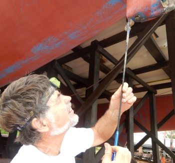 Extracting plastic bags with an automotive "grabber" |
Plastic Bag Screens
Much of the third world has a LOT of plastic garbage in the water. Motoring through this can get plastic
bags sucked up the leg of the saildrive. In 2019 we had to take the foot off our starboard saildrive,
and we found no less than 3(!) plastic bags stuck in the cavity at the joint. They couldn't have gotten
sucked through the 6 small holes just above the propeller, so they much have been sucked up the much larger
water intake at the "heel" of the sail‑drive. So we used a long grabber
(what is usually used to retrieve lost bolts in inaccessible places) up that water intake of our port saildrive
and retrieved 2 more plastic bags from it! Twisting the grabber once you grab a bag will make the
bag come out more easily.
Both Yanmar and Volvo saildrives have a large (1" or 25mm, square) water inlet in the "heel" of the foot (Yanmars have an additional set of much smaller inlets just above the propeller hub). In thinking about how to protect this area from further plastic bags, we eventually came up with the following neat and simple solution:
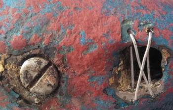 Screen across the water inlet at the saildrive heel |
That's it! Pretty simple once the boat is hauled out. Any plastic that can get through those small holes will flow easily up to our water strainers, but the bags will get stopped before getting sucked up the foot and getting into trouble.
In designing this with our cruising friends, we had some discussion about bi‑metallic action. Seizing wire is usually monel or stainless steel, which shouldn't react strongly with the aluminum of the saildrive. But you can also drill a slightly larger hole and strip the insulation off some thin electrical wire and thread the seizing wire through that insulation where it goes through the aluminum, if it makes you feel better.
Another approach might be to drill even larger holes and use plastic tie‑wraps (wire‑ties). These certainly won't react with the aluminum, but they'll also need to be replaced periodically, as they're both thicker and weaker than wire.
Replacing the water inlet valve
I'm not sure what Yanmar was thinking when they decided to use a multi‑turn valve to turn off the cooling
water, on the side of the saildrive. In seawater, calcium leeches out of the water and deposits itself
on the screw‑threads of the valve, jamming it so it can't be closed, which makes the valve pretty useless.
You can remove the valve and soak it in acid to remove the calcium, but you'd have to do it every few months,
and the boat almost has to be out of the water to remove that valve. Also, the acid could easily attack
parts of the valve as well as the calcium. Neither of our old valves EVER worked since we bought Ocelot.
The correct thing to do, of course, is to replace the silly multi‑turn valve with a good quality ball‑valve. We went with a stainless‑steel valve, but given that the saildrive is aluminum, plastic or bronze might be better. As with all ball‑valves, and especially those bought in 3rd‑world countries, make sure the handle is stainless‑steel as well. Many places sell cheaper valves with mild‑steel handles that just rust to bits in months.
| Is this useful? Buy us a beer! |
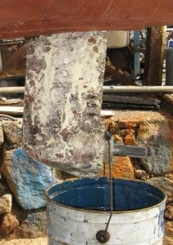 Draining oil. Note poor condition of saildrive paint compared to the hull |
Sealing the leg with epoxy
Most saildrives have an aluminum outer casing. If you paint this
casing with normal copper‑based antifouling paints, you run the risk of
bimetallic action eating up your saildrive. They sell special (non‑copper
based) antifouling paints to go on aluminum, but we've never found one that
lasted more than about 9 months before starting to allow growth. Since our
normal antifouling paints often last 2‑3 years, it's frustrating to have foul
saildrives on an otherwise clean hull. It's also a pain to have to buy and carry 2 different types of
antifouling paint.
In early 2010 we decided to clean our saildrives back to bare aluminum and then coat them in several layers of epoxy, to act as an insulating layer. Then we could use normal (long lasting) antifouling paints on the whole bottom, including the saildrives and props. As I write this (about a week after epoxy-coating and painting our saildrives) it all seemed to go quite well. Our West System epoxy went on like fine varnish, with no running or any signs of beading up or surface tension. We put 4 layers of epoxy on (in about 4 hours) before painting on the antifouling. (See the Update below, written 9 years later, for how well this worked.) We'll especially watch our zinc anodes, to see if they're dissolving faster than normal (the anodes we took off had been on for 3 years). If anyone else has experience with this, please let us know.
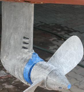 Epoxied & sanded saildrive & prop |
If you decide to do this yourself, make sure you read our article about how to make epoxy stick to aluminum. It's fairly straightforward to do, but it's not what the paint retailers will recommend. It involves stripping all old paint off your saildrives (a drill or small angle grinder with a fiber wheel will help tremendously here), cleaning the saildrives well with acetone or alcohol, painting on a good epoxy, and then sanding the aluminum through the wet epoxy (we typically use 80 grit wet/dry sandpaper). This will remove the oxide layer that forms on aluminum. Without any free oxygen near the aluminum, it will also prevent the oxide layer from forming again, allowing the epoxy a good chemical bond as well as a good mechanical key. The epoxy will turn aluminum colored from the sanded off aluminum, but that's OK. Only the first layer of epoxy needs to be sanded. If you're using a good epoxy that doesn't contain solvents (like West System epoxy) then the next layer of epoxy can be applied in about an hour, as soon as the under-layer has started to kick off. It should be mostly tack-free, but still soft enough to dig a fingernail into. This wet‑on‑wet approach will allow the epoxy to bond well to itself. If the epoxy is solvent free, then the first layer of antifouling can also be applied before the epoxy has fully hardened, but if you allow the epoxy to harden it should be lightly sanded and cleaned with acetone before applying the next coat.
If the epoxy you use has solvents or, even worse, oils or waxes, you'll need to wait until it hardens completely, then give each coat of epoxy a light sanding and wipe it down with acetone or alcohol to clean off any oils before applying the next coat. This will require 12‑24 hours between coats. Better to use a high‑quality epoxy if possible.
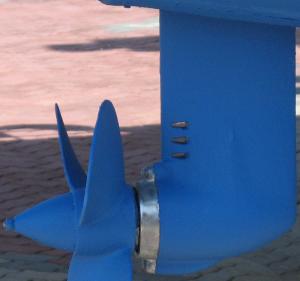 Finished saildrive and propeller |
Other things to look out for: Make sure you mask off your anodes well. Try hard to epoxy coat everywhere you might want to paint, as you don't want straight paint on bare aluminum if you can help it. This can be difficult around fiddly bits, like up under the rubber boot, or inside the water‑inlet holes. We sanded our water‑inlet holes by folding a bit of sandpaper into a thin strip and poking it through the holes, pulling it back and forth to sand as much as we could. You also need to be careful around the oil drain‑plug. The plug itself is steel and doesn't need epoxy, and you certainly don't want epoxy to get into the crack between the drain‑plug and the casing or into the screwdriver slot, so we'd recommend masking off the whole area for the epoxy phase. You might even consider squirting a bit of lanolin grease up into the crack with a plastic syringe (we keep a plastic syringe full of lanolin grease handy, as we're constantly using it).
The object of this whole exercise is to provide an insulating layer between the copper in the antifouling paint and the aluminum of the saildrive. Although the epoxy is only about 0.015" (0.4mm) thick, it should provide good electrical insulation. Since seawater is so conductive, there may still be a small bimetallic effect, but it should be easily absorbed by the zincs.
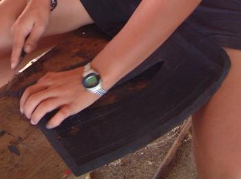 Amanda carving a new saildrive boot |
UPDATE: It's now 2019, 9 years since we first did this, and we have no complaints. Our external
zincs last 4‑5 years, typically. Our internal zincs last even longer. We do find that most times
when we haul, a bit of the epoxy has broken free, typically around the 6 water‑inlets just above the anode.
So we scrape it back to good epoxy, mask it off, and reapply another 4 coats over just the damaged area.
So a bit more maintenance, but the paint on the saildrives lasts as well as the rest of the hull, which is an
excellent trade‑off in our opinion. Plus, we don't have to buy 2 types of antifouling paint anymore.![]()
Saildrive Boots
Saildrives typically have a bit of rubber that goes between the saildrive and
the outside of the hull, to make for smooth water-flow around the saildrive.
Both the Yanmar and the Volvo parts are rather thin and flimsy, so they rarely
last more than a year or 2. Being official parts, they're also, of course,
quite expensive.
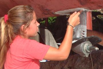 Amanda applying 5200 to both surfaces |
Both of the official parts actually contact the saildrive leg. This permits a good seal and good water‑flow around the leg, but it also allows engine (and saildrive) vibration to go through the boots, which will eventually tear up both the rubber boot itself as well as whatever adhesive you use to stick the boot to the hull.
In Tonga, our saildrive boots needed replacing. But the closest Yanmar dealer was in New Zealand, and getting parts out of them was like pulling teeth. They ignored our emails, even when we put EMERGENCY in big letters on the subject line. The only way we got their attention was to call them on a satellite phone ("Oh, THAT emergency email..."). Yeesh!
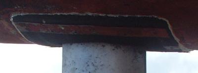 The finished (home-made) saildrive boot in place |
So instead of going through Yanmar, we went up to the local auto‑parts store and bought some truck mud‑flaps. These are thick (1/4" or 6mm) rubber, much sturdier than the standard Yanmar parts. Amanda carved these into the correct shape but left a small gap (again, about 1/4" or 6mm) between the boot and the saildrive. This still permits good water‑flow around the saildrives, but the boot would no longer be subjected to engine or saildrive vibration, so it should last much longer.
To hold these boots in place, we first tapered the edges, to provide less of an edge for things to grab onto. Then we forced them over the saildrives (the props have to be removed) and cleaned all surfaces thoroughly. Instead of using contact adhesive, we stuck the boots to the hull with fast‑cure 5200. Sika‑flex would probably have worked just as well since they're both polysulfide adhesives. Finally, we made stainless steel strips to go on the edges of the boots, and screwed through the strips and the boots into the hull. We replaced the starboard side flap in 2019, so it had lasted 15 years! (But while she was at it, Amanda carved a second pair of saildrive boots, just in case...)
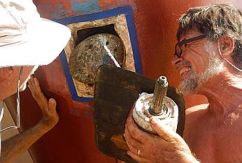 Removing (and reinstalling) the saildrive leg |
Removing and replacing the saildrive legs, and replacing the main diaphragm:
Sometimes it's necessary to remove the leg of the saildrive. We've had to replace the main diaphragm seal on both
sides, and we've also had some arguments with reefs that necessitated removing the legs. We also know boats where
water has crept into the oil from the leg joint, requiring replacing the O‑ring between the leg and the gearbox.
First, drain the oil, and remove the rubber "boot" that goes between the leg and the hull (and see our section on saildrive boots when replacing them).
On most boats, the saildrive is meant to be installed and removed from the top, and only the bulb at the bottom, housing the prop‑shaft bearings, has to go through the hull, so the opening often isn't very big. We strongly recommend grinding the hole to open it up a bit, as the flanges joining the 2 halves of the saildrive are 8.25" (21cm) in diameter. If you can't grind it open that much, grind it open as much as you can. It will help tremendously, especially when putting the leg back together. If you decide to open the hole up more once you've removed the leg, make sure you protect the gearbox from your grindings. You don't want fiberglass (or anything else) in the saildrive oil.
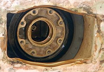 Bottom of gearbox, with hole widened a bit |
Looking up the hole, you should now be able to see the flange, with the 8 bolts holding it to the gearbox above. The bolts need an Allen‑key, so we use one from our socket‑set, with a long extension. Loosen the bolts as you would a car‑wheel, loosening one and then the bolt opposite that one, so you don't warp the flange. Loosen all the bolts a turn or 2, and then go back and remove them completely. Have someone help you hold the leg up before removing the last 2 bolts. If the hole in the hull isn't big enough, the leg may have to be tilted on its side to get it out.
The top of the lower driveshaft should be sticking out the top of the leg, possibly with the short joiner section that joins it to the upper driveshaft. If the joiner is not sitting on the lower driveshaft un‑stick it from the upper driveshaft in the gearbox and put it somewhere safe.
At this point, you can do whatever it was that you needed to do to the leg that required its removal.
If you're needing to replace the main diaphragm, there are some additional steps. Note that the service manual says that the main diaphragm needs to be replaced every few years. This is pure CYA hogwash. In 2019 we replaced our starboard diaphragm seal that we'd installed in Tonga in 2003, so it was 16 years old, and had sailed more than halfway around the world. It was in absolutely perfect condition. Once we cleaned some growth off it, we couldn't tell it from our new one, either in looks, toughness, or flexibility. So we'd say to replace the main diaphragm only when you need to, but it doesn't need to be replaced on a routine basis.
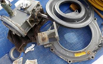 Gearbox, diaphragm, and diaphragm ring |
To replace the main diaphragm:
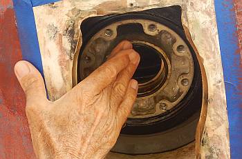 Gluing the O-ring to the gearbox (method #2) |
Replacing the leg:
First, clean both mating surfaces thoroughly. Make sure there are no dings or burrs or any debris that might keep the flanges from coming completely together. Run your fingers over the surfaces as sometimes you can feel things that you can't see. Pay special attention to the groove where the O‑ring will seat. If the O‑ring doesn't seal completely, water can get into the oil, so this is extremely important. You should also probably put the gearbox into gear, to keep the upper driveshaft from spinning.
There should be an O‑ring around the base of the cylindrical column that sticks out of the top of the leg. We just reused what was there when we replaced our diaphragms, and that worked, but the O‑ring should really be replaced if possible. And this is where it gets ticklish. The stock Yanmar O‑ring is 70mm in diameter and 3mm thick. But this is too big to fit snuggly on the leg. If you start with it there, you'll almost certainly pinch it against the gearbox and it won't seal correctly. So you have to put it inside the lip of the gearbox. But if you touch it with anything (like the lower driveshaft as you're trying to juggle it into position) then the O‑ring will fall out of position. And since you can't see it when it goes back together, you can't tell if it's properly positioned or not! Yanmar really only designed the leg to be reattached to the gearbox while on a workbench. But removing the gearbox from the engine so it can be worked on is a HUGE job.
Luckily, there are a few things you can do to help the situation (and these tricks, learned at the school of experience and hard knocks, are the main reason we're publishing this section).
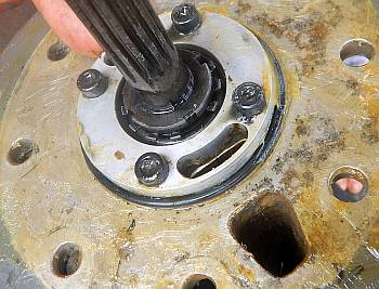 Smaller but thicker O-ring on the foot (better) |
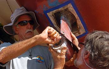 Twisting the propshaft so the splines can mesh |
You should now be ready for reassembly. Having 2‑3 people for this will help. Lift the leg up into the hole in the hull, line it up correctly, fit the flange‑guides into the correct holes, and slide the leg up the guides. Getting the driveshaft splines to mate can be tricky, but once you get the leg aligned correctly, push up gently while someone turns the propshaft gently back and forth until the splines mate and the leg slides up the last inch or 2. Then, while holding the leg up (don't let it slip down!) have someone run a couple of the flange‑bolts in finger tight. Then the leg can be let go, the guides removed, and the rest of the bolts screwed in. Tighten them in star order, like a car wheel, bringing them snug first, and then tightening them up to their correct torque.
If you want to epoxy coat the leg, this would be a good time to do that. See our sealing the leg with epoxy section above for instructions (even if you don't plan to use copper‑based antifouling paints, but just want to protect the leg).
Finally, slide the boot over the bulb at the bottom of the saildrive, up the leg, and fasten it in place. We usually use a mastic like quick‑dry 5200 and then stainless steel strips along each side with screws into the hull. See our saildrive boots section above for more.
Done!
| Is this useful? Buy us a beer! |
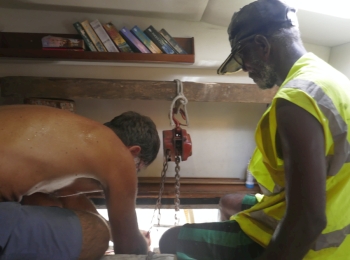 Rigging up the engine hoist in the aft cabin |
Replacing the oil seal on the input shaft from the engine
This, as they say, is a cow of a job, but when that seal starts leaking, it needs to be replaced. For
us, this happened to both of our saildrives at about 8300 hours. We noticed the oil level in our header
tank going down, and thick oil leaking out of the bottom of the bell‑housing between the engine and the
saildrive. On our port engine, this was accompanied by a grating noise like bearings trying to tear
themselves apart whenever the engine was on (not even in gear).
Taking out that gear‑cluster to replace the seal means you should really replace the bearings as well. You can order the seal (Yanmar #101158‑02220) and bearings (2, Yanmar #24141‑302060) from your favorite Yanmar dealer, but Yanmar doesn't actually make seals or bearings, and it's usually cheaper and easier to buy the generic parts (which are exactly the same as what Yanmar uses). The seals are: 62x40x8 (those are mm for OD, ID, & width). There are several bearing possibilities, but if you ask your bearing shop they can cross‑match them. We used 2 Timken 30206M‑90KM1 bearings, and when we removed our original "Yanmar" bearings, we found they were actually Timken bearings with that exact number on them!
The first time we did this, we hauled Ocelot out of the water, but the 2nd time there was no slip available so we did the job in the water. The difficult part is that you need to support the engine and slide it forward about 8" (20cm). For us, our engines are (mostly) under our aft beds, so we removed the cushions and built a wooden A‑frame to support a pair of chain‑hoists. The varnished wood under our beds was slippery enough to slide the A‑frame around, even when it was supporting our 4JH2 engine.
This procedure is very similar for SD‑20, SD‑30, and SD‑31 sail‑drives. Of course, if you have access to a sail‑drive service manual, that will show you more than I can here, and goes into more detail. This is more of a thumbnail sketch, more to help you decide if you want to do the job yourself or get help. It sounded pretty scary to us at first (Jon hates digging into gearboxes) but as usual, it turned out to be much easier once we got into it. We had a pair of mechanics do essentially the whole job in Kudat (NE Borneo) the first time we had to do it. The second time, we hired a mechanic to help, but he knew nothing about sail‑drives. Jon gave all the directions, but Peter helped, drifted the bearings out, and he ran the hydraulic press to put the bearings back.
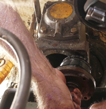 Extracting the input-shaft & gear-cluster |
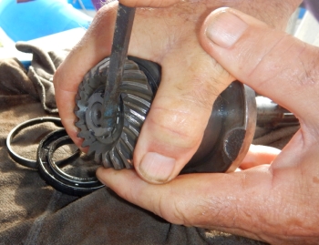 Tightening the nut on the new bearing cluster |
This took us about a day, or more precisely, 2 half‑days for each sail‑drive. It looks long, but there's nothing really that complicated. OK, a certified mechanic might shudder at the idea of putting a gearbox back together without measuring all sorts of clearances, but we decided that the sail‑drive was functioning pretty well before the seal let go, and nothing that we'd done was going to make that any worse. So it should be as good as it was before, and probably a bit better because of the new bearings, even without futzing with all the shims (that we didn't have).
Replacing the upper drive‑shaft
In the Solomon Islands we had a small argument with a reef. Don't ever do this - the reefs always win
these arguments.![]() One outcome of this
was that, since we were motoring at the time, we sheared the upper drive‑shaft, just above the sleeve that
joins it to the lower drive‑shaft (where the foot comes apart). We thought that replacing this was going
to be an ugly job, but it was really quite easy. Kudo's to the Yanmar designers for this one!
One outcome of this
was that, since we were motoring at the time, we sheared the upper drive‑shaft, just above the sleeve that
joins it to the lower drive‑shaft (where the foot comes apart). We thought that replacing this was going
to be an ugly job, but it was really quite easy. Kudo's to the Yanmar designers for this one!
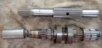 Broken driveshaft, with dog-clutch & needle bearings |
It turns out that nothing is really supporting that upper drive‑shaft except bearings, and those bearings aren't tight at all. In fact, the whole job can be done with the boat in the water! Although it's much less messy if you're hauled out and can drain the oil out of the saildrive first.
Yanmar's design has the bevel‑gear at the end of the (horizontal) input‑shaft mating to 2 bevel‑gears that ride on the vertical drive‑shaft. These 2 are always spinning, in opposite directions, whenever the engine is running. Between these 2 bevel‑gears is a small clutch that's splined to the drive‑shaft and can slide up or down to mate to either of the spinning bevel‑gears, thereby driving the shaft in either direction, forward or reverse. On SD‑20, 30, and 31, this dog‑clutch engages with a bit of a bang, but it's very positive. With later saildrives, Yanmar went to cone‑clutches, which apparently have a tendency to slip if not adjusted exactly right.
The bevel‑gears each have 3 bearings: a large outer bearing, and a pair of small needle‑bearings on the inside, between the gears and the shaft. Without taking the saildrive out of the boat, or even disconnecting it from the engine, it's pretty easy to replace 5 of the 6 bearings, as well as the shaft and the dog‑clutch. The large outer bearing around the lower bevel‑gear is trapped by the input shaft, and can't be removed until the input shaft is removed, but the inner needle‑bearings all come out when the shaft is lifted out.
As above, this procedure is very similar for SD‑20, SD‑30, and SD‑31 sail‑drives. Of course, if you have access to a sail‑drive service manual, that will show you more than I can here, and goes into more detail. This is more of a thumbnail sketch, to help you decide if you want to do the job yourself or get help. It sounded pretty scary to us at first but it turned out to be really easy once I got into it. I did all the work myself, with a bit of help to remove the old bearings from the outsides of the bevel‑gears. Since I had them open, I decided to replace all the bearings I could. Starboard was completely out of the boat, so I replaced all 6 bearings, but the dog‑clutch was fine. On port, I couldn't replace the big lower bearing without a lot more work, so I only replaced 5 of the 6 bearings, as well as the dog‑clutch, as it had been slipping recently and was badly worn.
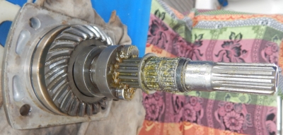 Saildrive top (left) with bearing, gear, dog-clutch & shaft |
Reassembly is essentially reversing the above. Slather everything in grease, of course.
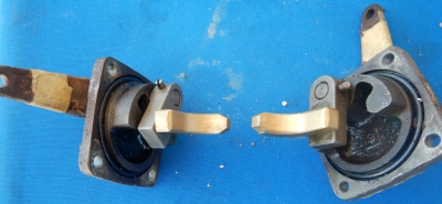 Shift mechanisms with new bronze shifters |
Taking the big outer bearings off the bevel‑gears is a bit of a challenge, as they're obviously pressed on. We held the bearings tightly in a big vice (squeeze it between 2 pieces of wood if you can) and used a pair of strong screwdrivers to apply pressure to separate the bearing from the gear. While one person was doing that, the other was hammering on a socket placed over the end of the gear, to pound the gear out from the inside of the bearing. It took some doing, but once we did the first one, the others went pretty easily. Pressing the new bearings onto the bevel‑gears is straightforward if you have a hydraulic press, but the service manual also talks about tapping them together with a hammer.
The shifter is bronze, and is running in a groove in the dog‑clutch (which is steel). The shifter can wear, which means the dog‑clutch may not fully engage the bevel‑gear, causing it to slip with a loud CLUNK every few seconds. We replaced the shifters on both sides, since we had them out. Replacing that shifter (Yanmar #196311‑06080) involves removing a tapered split‑pin to remove the arm from the shaft, and then removing the circlip that holds the shifter to the arm. It's extremely important to take photos or make drawings of exactly how it was put together before taking it apart, as it's very easy to put it back together backwards, especially when putting the arm back on the shaft. When replacing the shift mechanism back into the sail‑drive, make sure the shifter is sitting happily in the groove of the dog‑clutch before bolting everything back together.
Equipment Pages:
Cruising Info:
Top Level: Home | Destinations | Cruising Info | Underwater | Boat Guests | Ocelot | Sue | Jon | Amanda | Chris | Site Map | Make a Comment
|
If our information is useful, you can help by making a donation |
Copyright © 2000‑ Contact: Jon and Sue Hacking -- HackingFamily.com, svOcelot.com. All rights reserved.